Flight
Test III
Neutral Point Determination
For
The
KOPP BD-4 N375JK “Miss Daisy”
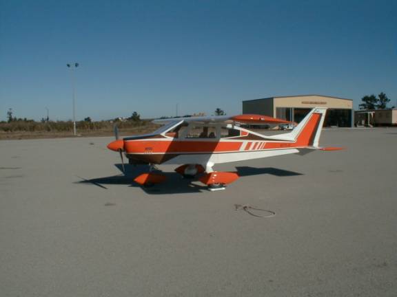
By LT Kenneth G. Kopp
Co-Builder/Owner of the Kopp BD-4 “Miss Daisy”
Table of Contents
List of Figures
Figure 1 Yoke Position vs. CL 22% c.g.
Figure 2 Yoke Position vs. CL 24% c.g.
Figure 3 Yoke Position vs. CL 25% c.g.
Figure 4 Yoke Position vs. CL 29% c.g.
Figure 5 Stick Fixed Neutral Point
vs. Cl
List of Tables
Table 1 Performance Summary Table
Table 2 Crew and altitude
assignments
Table 3 Flight Responsibilities
Table 6 Stick Fixed Neutral Points
Table 7 Kopp BD-4 Performance
Summary Table
Introduction
Longitudinal static
stability is an important aspect of an airplanes performance characterization
as it plays a fundamental role in the operation of the plane. An airplane is statically stable when forces
and moments exerted on the aircraft by
a disturbance tend initially to return the airplane to its equilibrium
position. For example, an airplane
trimmed in level flight encounters an upward wind gust causing the nose
of the airplane to pitch up; the
statically stable planes nose will initially pitch back toward its original
trim attitude, whereas the statically unstable airplane would continue to pitch
up until countered by pilot input or a stall occurs when its critical angle-of
–attack is exceeded. With this example in mind one might come to the conclusion
that airplanes should be designed with as much static stability as possible to
minimize overall pilot workload and aid in safe operation. Unfortunately it seems this line of
reasoning rarely comes cheap as an excess of static stability comes with the
price of reduced controllability. An
airplanes degree of static stability will cause it to react to forces generated
by control inputs in like manner to those of unwanted origin such as wind
gusts; thus requiring greater control force to effect maneuvering flight. Greater control force causes increased pilot
workload. The solution to this dilemma
lies in compromise according to the designed mission of the airplane. A Kopp BD-4, does not need the
maneuverability of a Navy SH-60B Seahawk attack helicopter (the pride of the
fleet).
For an airplane to be statically stable
(longitudinally) the following criteria must be met:
- Positive zero lift moment coefficient, CM,o
- Negative change in moment coefficient due to a change in angle of
attack

The term CM,c.g. is the moment coefficient
about the center of gravity of the airplane. ![]() is determined by the
following equation:
is determined by the
following equation:
![]() , where hc.g.
and hac are locations of the c.g. and aerodynamic center of the aircraft measured with respect to the leading
edge of the wing. This equation clearly shows the importance the
location of c.g. has in static stability.
The location of the c.g. (hc.g.) such that
, where hc.g.
and hac are locations of the c.g. and aerodynamic center of the aircraft measured with respect to the leading
edge of the wing. This equation clearly shows the importance the
location of c.g. has in static stability.
The location of the c.g. (hc.g.) such that ![]() = 0 is defined as the neutral point of the aircraft and is
often used as an alternate measure of static stability. When the c.g. is forward of the neutral
point (hn) the aircraft is statically stable. Conversely when the c.g. is aft of the neutral point the
aircraft is unstable. Therefore the difference between locations of neutral
point and c.g. (hn-h),
defined as static margin, is a positive
value for statically stable aircraft and negative for those that are unstable.
= 0 is defined as the neutral point of the aircraft and is
often used as an alternate measure of static stability. When the c.g. is forward of the neutral
point (hn) the aircraft is statically stable. Conversely when the c.g. is aft of the neutral point the
aircraft is unstable. Therefore the difference between locations of neutral
point and c.g. (hn-h),
defined as static margin, is a positive
value for statically stable aircraft and negative for those that are unstable.
The
purpose of flight test III is to determine the location of both stick fixed and
stick free neutral points to further build upon the Kopp BD-4 performance summary table initiated in flight test
I and expanded in flight test II. The
current performance summary table is shown below.
Table 1 Performance Summary Table
Altitude / Weight
|
Max Cl/Cd |
Min Thrust Required |
|
3000 ft / 1950 lbs |
8.8235 |
217.87 lbs |
|
7500 ft / 2130 lbs |
9.0329 |
229.63 lbs |
Parameters
|
Drag Polar
|
Power Curve
|
Cdo
|
0.0440
|
0.0425
|
e
|
0.7031
|
0.6507
|
|
Altitude |
Minimum
Thrust Horsepower Required |
|
|
3500
ft 1950 lbs |
52.33
HP |
|
|
7500
ft 2130 lbs |
60.59
HP |
|
|
Standardized
|
59.16
HP |
|
|
Vex
(Ias) |
75
mph |
|
|
Vie
(ias) |
90
mph |
|
|
R/Cmax
S.L max GW |
799
fpm |
|
|
AOCmax
S.L. max GW |
5.71° |
|
|
Service
Ceiling @ max GW |
10,600
ft |
|
|
Absolute
Ceiling @ max GW |
11,400
ft |
|
|
Kopp BD-4 Summary Table Test I conducted 27 July, 2000 Test II conducted 12 Aug, 2000 Data to be added upon further testing |
||
Part
I – Flight Test
General
Information
This test was conducted in the Kopp BD-4 on 24 Aug,
2000 departing from Monterey Peninsula Airport (MRY) at 10:00 am. Conditions at take-off were:
Wind: 290/8
Alt: 30.04
Sky Clear
Rwy: 28R
Crew and altitude assignments were as follows:
Table 2 Crew and altitude assignments
Crew – Stick free
|
Altitude |
Gross Weight (approx) |
|
LT Ken Kopp / Maj. Jim Hawkins |
5500 ft |
2025 lbs |
|
Crew – Stick Fixed |
Altitude |
Gross Weight (approx) |
|
LT Ken Kopp / Maj. Jim Hawkins |
5500 ft |
2025 lbs |
The test area was restricted to Salinas Valley from Salinas to 15 miles South East of King City. Crew coordination and a thorough test procedures briefing preceded each flight. Data collection sheets were developed, printed and discussed in detail prior to flight as well. Specific responsibilities were delegated as follows:
Table 3 Flight Responsibilities
|
Responsibility |
Pilot at the Controls |
Pilot Not at the Controls |
Flight Safety |
Primary |
Secondary |
|
Airwork |
Primary |
|
|
Test Procedure |
|
Primary |
|
Data Recording |
|
Primary |
|
Communications |
Primary |
Secondary |
|
Navigation |
Secondary |
Primary |
|
Visual Lookout |
Secondary |
Primary |
|
Emergencies |
Primary |
Secondary |
ATC flight following was utilized to the maximum extent possible to aid in collision
avoidance. King City and Salinas Muni were designated primary diverts in the event an emergency due to mechanical failure or weather occurred.
To minimize parallax error the left seat pilot remained at the controls while the right
seat pilot recorded data.
Flight Test Technique
Data necessary for determination of the stick fixed and free neutral points is obtained by measurement of stick (yoke) deflection and force throughout the aircrafts velocity range for different c.g. locations referenced to a nominal mid-range trim value. 120 mph was chosen as that trim airspeed for this aircraft. All yoke displacements and force measurements are made with respect to this initial position.
Four runs were completed at varying c.g. locations. The c.g. was changed by landing and rearranging previously measured ballast. Fuel was added as necessary to maintain a consistent gross weight between each run. In flight the aircraft was leveled at altitude, trimmed to 120 mph and the yoke displacement measured. Force measured at the trim airspeed is zero (by definition of “trim”). Airspeed was changed by climbing (diving) the aircraft while maintaining a constant power and trim setting. Once stabilized at the new airspeed the following parameters were recorded:
- Airspeed
- Altitude
- Rate of Climb (descent)
(based on timing between an initial and final altitude)
- OAT
- Stick Position
- Stick Force
To obtain stick force a Wagner FDL force dial was used to push (pull) the yoke against trim. Once stabilized the dial reading was recorded.
Part II – Data Reduction
Stick Fixed
All recorded data was
entered into an excel spreadsheet for data analysis. As was done in previous flight test all airspeeds and altitude
measurements are corrected for static position errors. Center of Gravity locations are commonly
referenced by the percent of the mean aerodynamic cord (%mac) the c.g. is aft of
the leading edge of the aircraft. The
Kopp BD-4’s MAC is 48” with the leading edge of the wing 75” aft of the nose cone, the reference point for all moment arms used
in weight and balance determination.
Subtracting the leading edge distance from c.g. locations and dividing
the result by the MAC results in c.g. location in terms of %mac. The following table displays the c.g.
locations flown during this test.
|
c.g. Location |
|
|
c.g. (inches) |
%mac |
|
85.63 |
22.15% |
|
86.49 |
23.94% |
|
87.2 |
25.42% |
|
89.12 |
29.42% |
The published c.g. limits for the Kopp BD-4 are
20.8% forward and 31.25% aft showing
the values flown cover a large portion of the entire c.g. range permitted.
With recorded data for altitude, OAT, A/S and ROC
(ROD) the aircrafts lift coefficient is
determined by:
Because an increment in c.g. location causes a proportional
increment in elevator position for a given airspeed (CL) and the
aircraft lift coefficient is proportional to angle of attack, determination of
the c.g. location where ![]() is the also the c.g.
location making
is the also the c.g.
location making ![]() =0 which is the
neutral point. Plots of stick position
vs. aircraft lift coefficient for each c.g. location are shown below.
=0 which is the
neutral point. Plots of stick position
vs. aircraft lift coefficient for each c.g. location are shown below.
Figure 1
Yoke Position vs. CL 22% c.g.
Figure 2
Yoke Position vs. CL 24% c.g.
Figure 3 Yoke Position vs. CL 25% c.g.
Figure 4 Yoke Position vs. CL 29% c.g.
Finding the values of ![]() is accomplished by
taking the first derivative of the curve fit equations from the plots of yoke
position vs. CL above.
Values of
is accomplished by
taking the first derivative of the curve fit equations from the plots of yoke
position vs. CL above.
Values of ![]() for each c.g.
location and CL are tabulated below.
for each c.g.
location and CL are tabulated below.
|
Stick Fixed Neutral Point (dyoke/dCL) |
||||
|
|
c.g. |
c.g. |
c.g. |
c.g. |
|
CL |
22.15 |
23.94 |
25.42 |
29.42 |
|
0.316 |
-5.36 |
-4.08 |
-4.70 |
-2.03 |
|
0.412 |
-4.15 |
-3.39 |
-3.71 |
-1.77 |
|
0.550 |
-2.73 |
-2.55 |
-2.57 |
-1.40 |
|
0.752 |
-1.31 |
-1.61 |
-1.48 |
-0.86 |
|
1.048 |
-0.62 |
-0.84 |
-1.12 |
-0.07 |
The stick free neutral point is determined by
plotting the values of ![]() vs. c.g. for each CL,
curve fitting and extrapolating each line to zero. The intersection of these curves with zero (x axis) is the
location of the neutral point for the given value of CL. A linear airplane will have a single point
of intersection indicating the neutral point is indeed a fixed point. A non-linear airplanes’ neutral point
becomes a function of CL. A
plot of
vs. c.g. for each CL,
curve fitting and extrapolating each line to zero. The intersection of these curves with zero (x axis) is the
location of the neutral point for the given value of CL. A linear airplane will have a single point
of intersection indicating the neutral point is indeed a fixed point. A non-linear airplanes’ neutral point
becomes a function of CL. A
plot of ![]() vs. c.g. is shown
below.
vs. c.g. is shown
below.
A table of the neutral points for each CL along
with a corresponding plot are shown below
Table 6 Stick Fixed Neutral Points
|
Stick Fixed Neutral Point vs. Cl |
||
|
CL |
NP |
|
|
0.3 |
34.5% |
|
|
0.4 |
35.5% |
|
|
0.5 |
37.5% |
|
|
0.7 |
42.0% |
|
|
1 |
33.0% |
|
Figure 5
Stick Fixed Neutral Point vs. Cl
Stick Free
Stick free neutral point is
determined in similar fashion. With
corresponding plots shown below.
Once again to locate the neutral point requires a plot of the slopes of each of the curves above vs. c.g. position as shown below.
According to the above plot the stick free neutral point is 82% mac.
Part III – Conclusions
The results obtained for the stick fixed neutral point are reasonable in that the aircraft will remain stable throughout its published range of c.g. locations. However, the neutral points were determined through linear curve fit with chi square values of about 84%. The fourth data point (aft most c.g.) was recorded during an additional flight because the reduced data from the original three data points resulted in unstable neutral points. This occurred because the range of c.g.’s was not great enough to cause sufficient data spread. Having personally flown the test flight, I feel confident the data was collected consistently and following proper procedure. This particular airplane has a significant amount of stabilator area and is an all-flying stab configuration. Yoke position changes with airspeed are very small compared to airplanes of similar performance and weight causing the data to fall into very tight groups when c.g. positions are located at intermediate values. This makes curve fit extrapolation to zero very susceptible to errors in measurement, friction in the control system and round-off errors. Taking the average range of stick fixed neutral points results in a value of 36.5% giving the Kopp BD-4 a static margin of 5.25% at the aft c.g. and 16.5% at the forward c.g..
The result of 82% stick free
neutral point must be discarded as invalid for two reasons. If the stick fixed results are accepted as
valid then a more stable stick free neutral point does not make sense. Secondly, recording an accurate force
measurement was extremely difficult because of variations in stick force
required during flight to maintain a constant airspeed. It is very difficult to hold an airspeed
against trim with a consistently constant force applied. The pilot is
continually making small corrections thereby changing the reading on the force
dial. Every attempt was made to
determine the average reading during a particular run.
Additionally, having recently spoken with the designer of the BD-4, Mr.
Jim Bede, he felt strongly the BD-4 was designed with little difference in
stick fixed and free neutral points.
This is mostly due to the configuration of the anti-servo trim tab that
prevents the stab from changing its trim position with hands free. This assertion has been confirmed by
trimming the aircraft and displacing the yoke against trim and releasing the
yoke. The yoke and airplane returns to
its trim position indicating very little friction or free play in the longitudinal flight control
system. The Kopp BD-4 summary table can
now be expanded to include the stick fixed neutral points.
Altitude / Weight
|
Max Cl/Cd |
Min Thrust Required |
|
3000 ft / 1950 lbs |
8.8235 |
217.87 lbs |
|
7500 ft / 2130 lbs |
9.0329 |
229.63 lbs |
Parameters
|
Drag Polar
|
Power Curve
|
Cdo
|
0.0440
|
0.0425
|
e
|
0.7031
|
0.6507
|
|
Altitude |
Minimum
Thrust Horsepower Required |
|
|
3500
ft 1950 lbs |
52.33
HP |
|
|
7500
ft 2130 lbs |
60.59
HP |
|
|
Standardized
|
59.16
HP |
|
|
Vx
(ias) |
75
mph |
|
|
Vy
(ias) |
90
mph |
|
|
R/Cmax
S.L max GW |
799
fpm |
|
|
AOCmax
S.L. max GW |
5.71° |
|
|
Service
Ceiling @ max GW |
10,600
ft |
|
|
Absolute
Ceiling @ max GW |
11,400
ft |
|
|
Longitudinal
Stability |
||
|
Stick
Free / Fixed Neutral Point |
36.5%
(mac) |
|
|
Forward
c.g. static margin |
16.5%
(mac) |
|
|
Aft
c.g. static margin |
5.25%
(mac) |
|